Your Legal Resource
Distortion Spectrum Shape Experiment
My View of Harmonic Distortion:
If you figure out what note on a piano each harmonic distortion product is, and then play the notes in conjunction with the fundamental, you find that the 2nd harmonic is the same as the fundamental but one octave higher (unless below about 100 HZ where the curve skews slightly - see the Audio Cyclopedia). The 3rd harmonic forms a major chord with the fundamental, which will enhance a song that is in a major scale, but will cause "dissonance" in a song that is in a minor scale. From there on, the higher-order harmonic distortion products are hit/miss as to whether or not they are pleasantly musically related to the fundamental. When you generate harmonic distortion products that extend way out from the fundamental, you get an accumulation of "notes" that aren't likely to be pleasantly musically related to the fundamental. It could be argued that this "noise" is then "modulating" the waveform. I wonder if there's a test for this kind of thing (?) This is the practical perspective on why higher-order harmonics are bad.
The presence of the 2nd harmonic is arguably always good (when it isn't the result of bad linearity and therefore high I.M. product generation). When measuring harmonic distortion, it is therefore arguable that the 2nd harmonic could be ignored. One might ask, "How far down are the harmonics after the 2nd?". If you symmetrically clip a sinewave, you will generate only odd harmonics. If you run a sinewave through a circuit where gain varies as a function of position on the dynamic range (typical of a heavily loaded pentode, for ex.), you get mostly even harmonics (maybe not as bad) but also the generation of intermodulation (I.M.) products (very bad). The ideal circuit would generate only the 2nd harmonic and have a very rapid roll off of any higher-order harmonics. A single-ended triode with a follower buffer seems to achieve this the best. The buffer is needed to keep the generation of I.M. products down.
On microdynamics, some wonder if the transformer core may be less linear as the waveshape goes thru zero magnetism in a push-pull topology... How much feedback is needed to correct that distortion? How much DC imbalance might be useful and practical here for the sake of microdynamic linearity? What if we used two separate SE output transformers, and then tied their output windings together? Just something to think about.
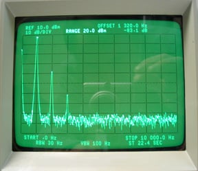
My own spectrum analysis testing of a transformer-coupled push-pull EL34 output stage showed nothing at all beyond the 3rd harmonic distortion product.
Blocking distortion is where the tube is driven into saturation during peaks to the point where grid current flows, which causes a negative DC charge to accumulate on the coupling cap at the grid, relative to the other side of the cap which is ultimately effectively connected to the cathode of the tube in question. When the sinewave input signal directs the tube back to the zero crossings, this charge causes it to get there too soon by providing an additional negative bias. The tube stays in cutoff until the DC on the cap can discharge, or be overcome by a bigger drive signal. The shift in amplitude is one thing, but the delay that this can cause creates substantial crossover distortion. This is a distortion that is relatively unpleasant and is hard on speaker drivers due to its sharp corners. The Dynaco Stereo 70 has this, but because of the huge imbalance in the source impedances coming from the phase splitter, the crossover distortion actually rises up the sinewave as you push the amp further and further into overdrive. This may make it slightly less audible. It's been said that the only way to be sure this will never happen is to drive the output tubes with interstage transformers ($90 + each) or drive them with directly coupled cathode followers (so I'm told), or by making it impossible for the EL34's to be driven to within a volt of zero bias somehow.
In the typical RC coupled circuit, it's best to use as small a cap as is practical, and as big a grid stopper resistor as is practical to reduce grid current flow during these times of overload (a bigger grid stopper resistor will take away from phase margin at the high end, so be aware).